4 9 Ford Engine Firing Order Diagram -3 Way Switch Schematic is free HD wallpaper. This wallpaper was uploaded at February 11, 2021 upload by admin in Diagram.

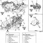
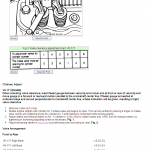
Ford 2.9 V6 Firing Order - It's essential to know which bank (or cylinder head) is number 1 to assist establish a starting place for firing order or simply to change the proper aspect, as an Oxygen sensor, gas injector or ignition coil.
Ford 2.9 V6 Firing Order - It's crucial that you know which lender
4 9 Ford Engine Firing Order Diagram -3 Way Switch Schematic in your computer by clicking resolution image in Download by size:. Don't forget to rate and comment if you interest with this wallpaper.
More Collection of 4 9 Ford Engine Firing Order Diagram -3 Way Switch Schematic